
How to Calculate Load-Carrying Capacity of Conveyor Rollers
Overview
Getting the load capacity right is a balancing act. Under-designing a conveyor system can lead to component damage and system failure, while over-designing can easily push a project over budget. The calculation itself relies on simple arithmetic.
Step-by-Step Calculation Example
The article demonstrates the calculation using a sample design scenario for a Gravity Roller Conveyor System handling carton boxes.
- Carton Box Weight: 50 kg
- Length of Box: 400 mm
- Width of Box: 300 mm
1. Determine Roller Width
To ensure stable movement, add a clearance margin to the width of the product.
Formula: Width of carton box + 50 mm
Calculation: 300 mm + 50 mm = 350 mm roller length
2. Determine Roller Pitch (Center-to-Center Distance)
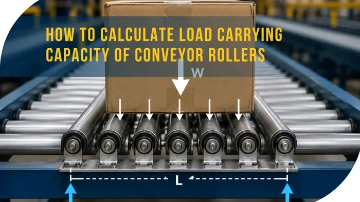
To keep any product stable as it travels, a minimum of 3 rollers must support it at any given time (assuming the product's weight is evenly distributed).
Target Pitch: 400 mm (Box Length) / 3 rollers = 133.3 mm
Safety Margin Selection: To be safe, the pitch is rounded down to 100 mm.
3. Calculate Load per Roller
With a 100 mm pitch and a 400 mm box length, there will actually be 4 rollers underneath the box at any given moment.
Weight Distribution: The 50 kg load is split across those 4 rollers.
Calculation: 50 kg / 4 rollers = 12.5 kg per roller
Final Requirement: The system requires conveyor rollers that can reliably support a 12.5 kg load over a length of 350 mm.
Roller Load Capacity Chart (Length vs. Capacity)
Below chart provides Roller Length (mm) x Capacity (Kg) for our standard roller diameter and thickness combinations. Use this as a quick reference once you have calculated the required roller length and load per roller.
| Roller Dia x Thickness (mm) | 200mm | 300mm | 400mm | 600mm | 800mm | 1000mm | 1300mm | 1600mm | 1800mm |
|---|---|---|---|---|---|---|---|---|---|
| 31.75 x 1.6 | 100 | 80 | 50 | 30 | x | x | x | x | x |
| 38.1 x 1.6 | 150 | 120 | 90 | 60 | 30 | x | x | x | x |
| 50.8 x 1.6 | 170 | 170 | 150 | 120 | 100 | 80 | x | x | x |
| 60.3 x 1.6 | 200 | 180 | 160 | 150 | 130 | 100 | 80 | x | x |
| 60.3 x 2.5 | 300 | 300 | 300 | 300 | 250 | 200 | 100 | 70 | x |
| 76.2 x 3 | 500 | 450 | 450 | 450 | 450 | 400 | 400 | 300 | x |
| 90 x 3 | 500 | 500 | 500 | 500 | 500 | 450 | 400 | 400 | 300 |
x — we do not recommend the lengths for the said roller dia. Values are load capacity in Kg per roller and are for reference and indicative purposes only; actual capacity varies with material, bearing type, loading conditions, and operating environment.
Crucial Design Variables
While static charts provide a strong starting point, published capacities are purely indicative. Real-world engineering must factor in:
- Concentricity: Whether the weight distribution of the product is perfectly centered or uneven.
- Impact Loading: The shock forces generated when a component or box is dropped or loaded onto the conveyor line.
Formulas
Structured breakdown of the calculation formulas and safety factors:
Roller Width Formula
$$\text{Roller Width} = \text{Product Width} + 50\ \text{mm}$$
Maximum Pitch Formula (Stability Constraint)
$$\text{Max Roller Pitch (C-C)} = \frac{\text{Product Length}}{3}$$
Load per Roller Formula
$$\text{Load per Roller} = \frac{\text{Total Product Weight}}{\text{Number of Rollers Directly Underneath}}$$
Key Engineering Considerations
- Weight Concentricity: The math assumes perfectly uniform weight distribution. If a box is packed heavily on one side, specific rollers will experience much higher stress than the calculated average.
- Impact Dynamic Loading: If objects are dropped or roughly fed onto the line rather than slid smoothly, the instantaneous impact force can spike past the static baseline, requiring higher-capacity bearings or thicker roller walls.
Use the arithmetic as a baseline and always review roller selection against expected dynamic conditions and the manufacturer's published data.